|
||||||||||||||||||||||||||||||||||||||
|
Programming
Memory Management Background-Process Keyboard Memory ManagementThe RAM memory of the C64 is 64K bytes. The most important chip in the C64 is the Video-Chip VIC-II. This controls the CPU, the complete screen, displays the characters, the sprites and the bitmap graphics. The 64K byte RAM and the 4K byte character ROM is the source of what the VIC-II will display on the screen. It fetches the sprite and bitmap data from the RAM, and in the case of changed character sets stored in RAM, also the characters from RAM. This happens completely automatically. But how does this automatic process work? By telling the VIC-II which memory area it should use for the characters, sprites and bitmap graphics.The VIC-II can use 16K of this 64K RAM of the C64. This 16K is called the BANK. There are 4 of them, because 16K divided by 64K are 4 banks. Which 16K RAM bank the VIC-II is currently using is controlled by the CIA 2 with its PORT A and the bits 0 and 1. To simplify the control and programming, I have created a visual memory configurator with which you can define the desired memory allocation with a few mouse clicks. Then immediately the necessary code is copied into the textarea down below: Background-ProcessOne of the most important possibilities of the C64 is to execute program code at a certain time by interrupting the main program (this is called interrupt) and jumping to the background program via a previously defined jump address, and then return to the main program.Here an example: The so-called "raster line interrupt" is used most frequently. This interrupts the the main program is interrupted when a certain raster line is reached and you want to important changes, such as changing the frame color, are to be made. change:
This way you can also create a split screen with a bitmap at the top and characters/text at the bottom. C64 KeyboardLooking for simple, good and correct information about C64 keyboard programming and how exactly the C64 keyboard works, I found nothing suitable. Either the presentations were wrong, not good to read, confusing or completely overloaded with endless detailed information.For this reason, I myself have created a very short and lucid explanation, as well as an example, which shows and explains the essential things (please look at the picture below first)." The top horizontal row ("Write") represents the CIA port A with IC pins 2-9 (COLUMN: PA0-PA7). With the following commands we switch the CIA pins 2-9 (PA0-PA7) to "OUTPUT": LDA #$FF ; %11111111 ($FF) (1= OUTPUT, 0 = INPUT) STA $DC02 ; PA0-PA7 Direction: "Output" The left vertical row ("Read") represents the CIA port B with IC pins 10-17 (ROW: PB0-PB7) With the following commands we switch the CIA pins 10-17 (PB0-PB7) to "INPUT": LDA #$00 ; %00000000 ($00) (1= OUTPUT, 0 = INPUT) STA $DC03 ; PB0-PB7 Direction: "Input" 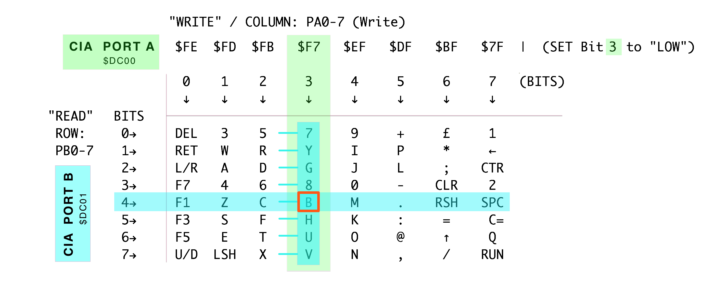
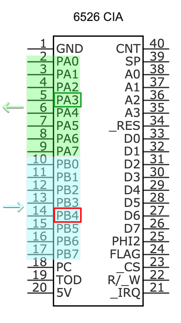
How to read the C64 keyboard: // * All pins of PORT A and PORT B are "HIGH" (internal Pull-Up Resistors) * 1. In the CIA PORT A the BIT 3 is set to "LOW", for this we write in $DC00 a $F7 (%11110111) LOOP LDA #$F7 STA $DC00 ; Set BIT 3 "PA3" to "LOW" (COLUMN 3) 2. The ROW byte of $DC01 is read from CIA PORT B, if BIT 4 is "LOW" (%11101111) the key "B" is pressed. LDA $DC01 ; Read PB0-PB7 ... BIT 4 "LOW"? Yes: Key "B" pressed STA $0400 ; print value on screen JMP LOOP Attached is a picture that shows which "CIA PORT A" PA0-PA7 columns (Pins 2-9) belong to which keys: 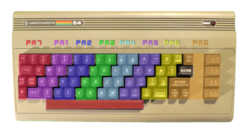
|
||||||||||||||||||||||||||||||||||||||